
13 Dynamics
Dynamics
Concepts and Principles
To study the dynamics of an arbitrary rigid body we will break the motion down into a pure translation of the CM and a pure rotation about the CM. We will use particle dynamics, i.e., Newton’s second law applied to the CM of the object, to study the translational portion of the motion. The study of the rotational portion of the motion requires a pair of new concepts. We will “invent” these concepts through the use of an analogy with linear dynamics.
In linear dynamics, Newton’s second law states that the linear acceleration of an object is proportional to the total force acting on the object and inversely proportional to the mass, or inertia, of the object. It would seem plausible that the angular acceleration of an object would depend on analogous concepts in the same manner.
We will replace the concept of force, often thought of as the push or pull applied to an object, with a quantity measuring the twist applied to an object. We will call this new quantity torque, symbolized t.
We will replace the concept of mass, the measure of the resistance of the object to changes in its linear velocity, with a quantity measuring the resistance of the object to changes in its angular velocity. We will call this new quantity rotational inertia, symbolized I.
In summary,
Before we go any further, however, let’s define these new concepts more clearly.
Torque
In simple English, torque measures the twist applied to an object. The question remains, however, how do we quantify twist?
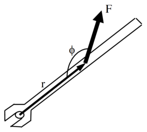 |
Let’s examine a common device used to generate twist, a wrench. The magnitude, location, and orientation of the force applied to the wrench by the person’s hand are indicated. Each of these three parameters effects the amount of twist the person delivers to the wrench (and therefore to the bolt).
|
If you’ve turned many bolts in your life, two things about this person’s bolt-turning technique should grab you. First, why is this person applying the force at such a silly angle? She would generate much more twist if she applied the same magnitude force perpendicular to the wrench, rather than at an angle far from 900. Second, why is she not applying the force at the far edge of the wrench? She would generate far more twist if she applied the same magnitude force at the far edge of the wrench.
If the preceding paragraph makes sense to you, you understand how to quantify torque. To maximize torque, you should:
- Apply the force far from the axis of rotation (the bolt).
- Apply the force perpendicular to the position vector between the axis of rotation and the force.
- Apply a large magnitude force.
Mathematically, this is summarized by:
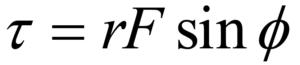
Note that this function has a maximum when r is large, F is large, and f = 900. Torque will also be assigned a direction, either clockwise or counterclockwise, depending upon the direction of the twist applied to the object.
Rotational Inertia
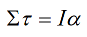
We have constructed a rotational analogy to Newton’s second law,
Our next task is to better define what we mean by I, the rotational inertia.
The rotational inertia is a measure of the resistance of the object to changes in its angular velocity. Imagine applying the same torque to two objects, initially at rest. After applying the torques for some set amount of time, measure the angular velocity of the objects. The object with the smaller angular velocity has the larger rotational inertia, because it has the larger resistance to angular acceleration.
Since more massive objects are harder to get moving linearly, it seems plausible that rotational inertia should depend on the mass of the object. It also seems plausible that rotational inertia should depend on the shape of the object.
 |
For example, it would be easier to get the smaller dumbbell spinning than the larger dumbbell, even though they have the same total mass.
Let’s try to get more quantitative. Examining
we can see that the units of I must be the units of torque (N.m) divided by the units of angular acceleration (s-2). Remembering that a Newton is equivalent to kg.m.s-2 leads to the units of rotational inertia being kg.m2. Thus, rotational inertia must be the product of a mass and a distance squared. |
It seems plausible (there’s that word again!) that the distance that is squared in the relationship for rotational inertia is the distance from the rotation axis. The farther a piece of mass is from the rotation axis, the more difficult it is to give the object an angular acceleration.
 |
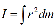
Enough with the “plausibilities”, let’s finally just define the rotational inertia to be:
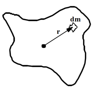
Imagine the object of interest divided into a large number of infinitesimally small chunks of mass, each with mass dm. Each chunk of mass is a distance r from the rotation axis. If you take the product of the mass of each chunk and the distance of the chunk from the rotation axis, squared, and sum this quantity over all the chunks of mass, you have the rotational inertia of the object of interest. |
In summary, we now have quantitative relationships for measuring torque and rotational inertia,
and the hypothesis that these two quantities are related in a manner analogous to Newton’s second law,
Analysis Tools
Calculating the Rotational Inertia
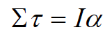
To fully utilize Newton’s second law in rotational form, we must be able to set up and evaluate the integral that determines the rotational inertia. (To be honest, this is a lie. For the vast majority of common shapes, and many quite uncommon shapes, these integrals have already been evaluated. A table of selected results is at the end of this section.) To test our understanding of the relationship for rotational inertia, let’s calculate the rotational inertia for a thin disk about an axis passing through its center of mass and perpendicular to its circular face.
 |
1. Choose the chunks of mass, dm, to be ring-shaped. This is because you must multiply each dm by the distance of the chunk from the rotation axis squared. To facilitate doing this, it’s crucial that every point in the chunk be the same distance from the axis, i.e., have the same r. If the ring-shaped chunk is thin enough, for example dr (infinitesimally) thick, then this is true.
|
- Realize that the mass of the little chunk is directly proportional to its volume, assuming the disk has a constant density. If it does have a constant density, the ratio of the chunk’s mass to its volume must be the same as the ratio of the total mass of the disk to its volume.
where R is the radius of the disk and T is its thickness. The volume of the ring-shaped chunk, dV, is equal to the product of the circumference of the ring (2pr), the thickness of the disk (T), and the thickness of the ring (dr). Thus,
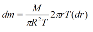
- Plug the expression for dm into
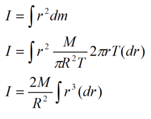
To include all the chunks of mass, the integral must go from r = 0 m up to r = R.

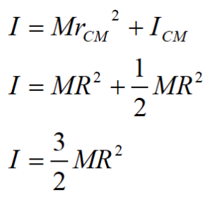
Thus, the rotational inertia of a thin disk about an axis through its CM is the product of one-half the total mass of the disk and the square of its radius. Notice that the thickness of the disk does not effect its rotational inertia. A consequence of this fact is that a cylinder has the same rotational inertia as a disk, when rotated about an axis through its CM and perpendicular to its circular face.
The Parallel-Axis Theorem
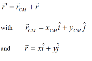
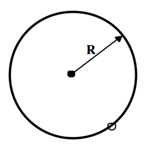
Now let’s imagine we need to calculate the rotational inertia of a thin disk about an axis perpendicular to its circular face and along the edge of the disk. It would be convenient if we could determine the rotational inertia about an axis along the edge using the rotational inertia about an axis through the CM (which we’ve already calculated). In fact, there is a very convenient method to determine the rotational inertia about any axis parallel to an axis through the CM if we know the rotational inertia about an axis through the CM.
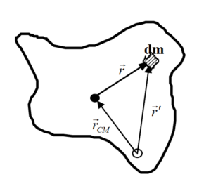 |
Imagine you want to determine the rotational inertia of an arbitrarily shaped object about an arbitrary axis. The solid circle denotes an axis through the CM, the hollow circle the axis of interest. The two axes are parallel.
Notice that
|
Thus,
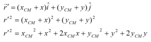
The rotational inertia about the axis of interest is given by:
Note that xCM , yCM , and rCM are constants that depend only on the distance between the two axes. Thus, xCM , yCM , and rCM can by brought outside of the integral.
![]()
Now comes the key observation in the derivation. Examine the term ò x dm. Remember that x is the horizontal distance from the CM. If this distance is integrated over all the chunks of mass, dm, throughout the entire object, this integral must equal zero because the CM is defined to be in exactly the spot where a mass-weighted average over distance is equal to zero. ò x dm and ò y dm are equal to zero by the definition of CM! (Pretty cool, huh?)
Thus,
Noting that ò dm is the total mass of the object, M, and ò r2 dm is the rotational inertia about the CM, ICM, then
This result states that the rotational inertia about an axis parallel to an axis through the CM, I, is equal to the rotational inertia about an axis through the CM, ICM, plus the product of the total mass of the object and the distance between the axes, rCM, squared.
 |
To answer the original question, let’s determine the rotational inertia of a thin disk about an axis perpendicular to its circular face and along the edge of the disk using the parallel-axis theorem.
We know that the rotational inertia for a thin disk about an axis passing through its center of mass and perpendicular to its circular face is 1/2 MR2 and that the distance between the CM axis and the axis of interest is R. Thus,
|
Applying Newton’s Second Law in Translational and Rotational Form – I
Investigate the scenario described below.
|
The robotic arm at right consists of a pair of hydraulic jacks, each attached 10 cm from the pin “elbow”. The elbow is 15 cm from the extreme edge of the 40 kg, 0.90 m long “forearm”. The forearm and attached 90 kg load are held stationary at an angle of 20° below horizontal. Since the jacks primarily exert forces through extension, the front, or “biceps”, jack is exerting negligible force.
|
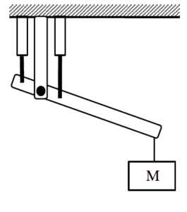 |
To study the dynamics of this situation, we will first need a free-body diagram of the forearm (and the attached load).
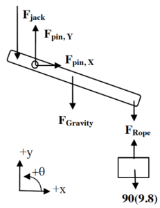 |
The forces due to the jack, the rope, and gravity should not need much explanation. However, the forces due to the pin elbow may need some explanation. First, the free-body diagram drawn at left is of the forearm, not including the pin that serves as the elbow. Thus, the pin is external to the object of interest, and thus its interactions with the object are forces that must be indicated on the diagram. If you were to include the pin as part of the forearm, then the upper part of the arm would be external to the object of interest (pin plus forearm) and its interactions with the “pin plus forearm” would have to be indicated as forces on the diagram. Both of these approaches are completely valid. |
Second, the direction of the force of the pin on the forearm may not be obvious. Does the pin push straight down on the forearm, pull up on the elbow, or push at some unspecified angle? The only thing that’s clear is that this force is directed somewhere in the xy-plane. If the force is in the xy-plane, then it must have components along both the x- and y-axis (although one of these components may turn out to have a magnitude of zero). Thus, to handle the generality of the situation you should include both an x- and y-component for the force of the pin on the forearm. For convenience, I’ll draw these forces as pointing in the positive x and y directions. (If my guess is wrong, the mathematics will tell me.)
Now that we have a free-body diagram, we can apply Newton’s second law, both the linear form (in the x- and y-directions) and the rotational form (in the q-direction).
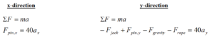
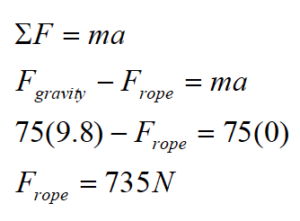
Since the forearm is held stationary, both ax and ay are equal to zero. Also, Frope is equal to the force of gravity on the load, 882 N.
![]()
Obviously, we need another equation in order to determine the two unknown forces. The obvious choice is Newton’s second law in rotational form.
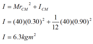
Before we begin, we should determine the rotational inertia for a thin rod (the closest thing to a forearm in our table) rotated about an axis not at its CM. A thin rod rotated about its CM has rotational inertia 1/12 ML2. We are interested in its rotational inertia about an axis not at its CM, so we must use the parallel-axis theorem with rCM = 0.30 m. (The CM is at the center of the forearm, 0.45 m from either end. Since the elbow is 0.15 m from one end, the distance between the elbow and the CM is 0.30 m.) Thus,
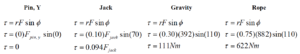
We must also determine the torque due to each force. (Remember, the angle, f, in the relation for torque is the angle between r (oriented along the forearm) and F.)
Finally, let’s apply Newton’s second law in rotational form, paying careful attention to the algebraic sign of each torque. Note that our coordinate system indicates that all torques acting counterclockwise are positive. Therefore, all torques acting clockwise are negative.
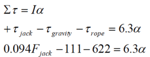
Since the forearm is held stationary, a is equal to zero.
The jack must exert a force of 7796 N to hold the forearm stationary.
Plugging this value into our y-equation yields:
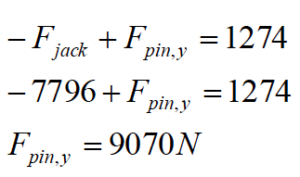
The pin must exert a force of 9070 N upwards, since the mathematics determined that the algebraic sign of FPin,y was positive.
Applying Newton’s Second Law in Translational and Rotational Form – II
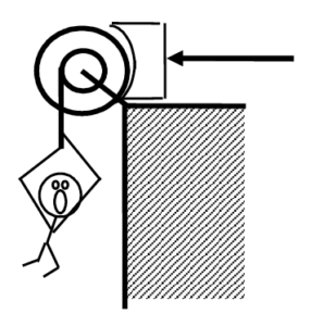
|
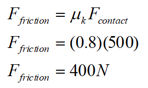
A 75 kg man is attached to a rope wrapped around a 35 kg disk-shaped pulley, with inner and outer diameters 0.60 m and 0.90 m, respectively. The man is initially at rest. The brake shoe is pressed against the pulley with a force of 500 N. The coefficient of friction between the brake shoe and the pulley is (0.9, 0.8). |
 |
First, we have to determine whether the force applied to the brake shoe is sufficient to hold the man stationary. If it’s not, we have to find the man’s acceleration. To accomplish this, we need free-body diagrams for both the man and the pulley.
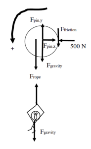 |
We’ll use counterclockwise as the positive q-direction and down as the positive y-direction.
The pin, or axle, at the center of the pulley exerts forces in the x- and y-direction, although the exact directions may be unknown. We’ll just label these forces as Fpin,x and Fpin,y. The frictional force that acts on the right edge of the pulley acts in a way to prevent the man from falling (or, if he does fall, to slow down the man’s fall).
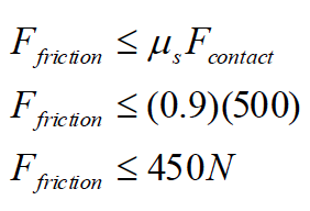
To begin my analysis, I’ll assume that the man is stationary, solve for the value of the frictional force required to keep him stationary, and then determine whether this frictional force is possible given the applied force of 500 N and the coefficient of static friction.
|
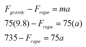
Let’s apply Newton’s second law to the man in the y-direction. (Remember, we are assuming he is not falling.)
Now look at Newton’s second law applied to the pulley in the q-direction.
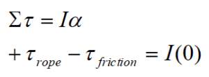
Notice that all of the other forces acting on the pulley do not exert torques on the pulley. They are either located at r = 0 m or have angular orientations of f = 180°.
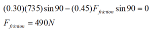
Therefore, to hold the man stationary requires 490 N of friction. However,
Therefore, the man must accelerate downward.
Now that we know the man must fall, let’s write the same two equations as before, although this time the accelerations (both angular for the pulley and linear for the man) are not zero.
For the pulley:
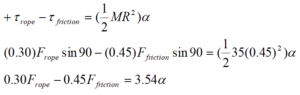
This assumes that the rotational inertia of a “compound” pulley, one with more than one location where a rope can be wrapped, is the same as a regular pulley, and that the outermost radius of the pulley determines the inertia.
Since the man is falling, the frictional force is now kinetic, and
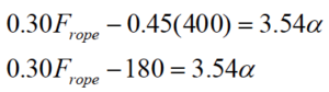
Thus our “pulley” equation becomes:
Examining Newton’s second law for the man,
We now have two equations with three variables. However, the angular acceleration of the pulley and the linear acceleration of the man are directly related. Since the rope that the man is attached to is wrapped 0.3 m from the center of the pulley, the man accelerates at the same rate as the tangential acceleration of a point on the pulley 0.3 m from the center. Thus,
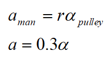
Using this relationship allows me to rewrite the two Newton’s second law equations as:
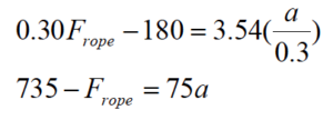
This pair of equations has the solution
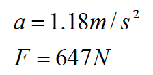
The man falls with this acceleration and the rope exerts this force (upward on the man and downward on the pulley).
Applying Newton’s Second Law to Rolling Motion
|
The child at right is pretending to be a steamroller by pushing a 24 kg, 0.60 m radius cylindrical object around his backyard. The boy pushes horizontally with a force of 70 N. The coefficient of friction between the cylinder and the ground is (0.5, 0.4). |
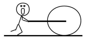 |
Let’s draw a free-body diagram and write Newton’s second law in the x-, y-, and q-directions.
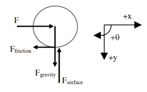
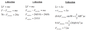
Note that the description does not specify whether the cylinder rolls or skids when the child pushes it. We will have to make an assumption, continue with the calculation, and then check our assumption for validity. Let’s assume that the bottom of the cylinder does not slip in its contact with the ground, which means the cylinder rolls without slipping around the backyard.
If the cylinder bottom does not slip in its contact with the ground, the horizontal acceleration (and velocity) of the cylinder bottom must equal zero. Since the acceleration of the cylinder bottom is the sum of the acceleration due to translation of the CM and the acceleration due to rotation about the CM, for the bottom to have zero horizontal acceleration means that the acceleration due to rotation,
![]()
must be equal in magnitude, and opposite in direction, to the translational acceleration of the CM. Thus,
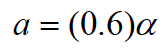
Combining this with our y- and q-equations yields:
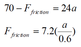
This pair of equations has the solution
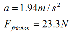
Now we must check the validity of our assumption. If the cylinder rolls without slipping, the frictional force is static. Thus,
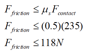
Since our calculated value for Ffriction is less than 118 N, the cylinder does remain in static contact with the ground during its motion, our assumption is validated, and our numerical results are correct.
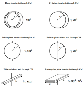
Rotational Inertia of Common, Uniform Solids
Activities
The wrench below has six equal magnitude forces acting on it.
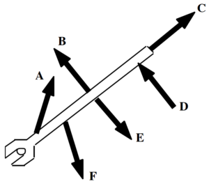
Rank these forces on the basis of the magnitude of the torque they apply to the wrench, measured about an axis centered on the bolt.
Largest 1. _____ 2. _____ 3. _____ 4. _____ 5. _____ 6. _____ Smallest
_____ The ranking cannot be determined based on the information provided.
Explain the reason for your ranking:
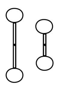
Two identical spheres are attached together by a thin rod. The rod lies on a line connecting the centers-of-mass of the two spheres. The length of the rod is equal to the diameter of each sphere. The object has six equal magnitude forces acting on it at the locations shown.
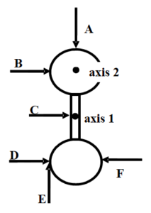
Rank these forces on the basis of the torque they apply to the object, measured about axis 1. Let the counterclockwise direction be positive.
Largest Positive 1. _____ 2. _____ 3. _____ 4. _____ 5. _____ 6. _____ Largest Negative
_____ The ranking cannot be determined based on the information provided.
Explain the reason for your ranking:
Rank these forces on the basis of the torque they apply to the object, measured about axis 2. Let the counterclockwise direction be positive.
Largest Positive 1. _____ 2. _____ 3. _____ 4. _____ 5. _____ 6. _____ Largest Negative
_____ The ranking cannot be determined based on the information provided.
Explain the reason for your ranking:
An artist constructs the mobile shown below. The highest two crossbars are 3 units long, and are hung from a point ⅓ along their length. The lower three crossbars are 2 units long, and are hung from their midpoint. In this configuration, the mobile is perfectly balanced.
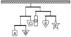
Rank the masses of the six hanging shapes.
Largest 1. _____ 2. _____ 3. _____ 4. _____ 5. _____ 6. _____ Smallest
_____ The ranking cannot be determined based on the information provided.
Explain the reason for your ranking:
An artist constructs the mobile shown below. The crossbars are either 3 units long, and hung from a point ⅓ along their length, or are 2 units long, and hung from their midpoint. In this configuration, the mobile is perfectly balanced.
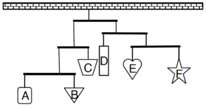
Rank the masses of the six hanging shapes.
Largest 1. _____ 2. _____ 3. _____ 4. _____ 5. _____ 6. _____ Smallest
_____ The ranking cannot be determined based on the information provided.
Explain the reason for your ranking:
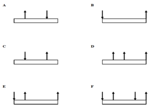
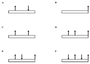
The six platforms below are initially at rest in deep space. The indicated forces act on the platforms at their endpoints, quarter-points, or midpoints. All forces have the same magnitude.

Rank these platforms on the basis of the torque that acts on them, measured about their CM. Let the counterclockwise direction be positive.
Largest Positive 1. _____ 2. _____ 3. _____ 4. _____ 5. _____ 6. _____ Largest Negative
_____ The ranking cannot be determined based on the information provided.
Explain the reason for your ranking:
The six platforms below are initially at rest in deep space. The indicated forces act on the platforms at their endpoints, quarter-points, or midpoints. All forces have the same magnitude.
Rank these platforms on the basis of the force that must be applied to them, at their left-edge, to keep them from rotating. Let the positive direction be upward.
Largest Positive 1. _____ 2. _____ 3. _____ 4. _____ 5. _____ 6. _____ Largest Negative
_____ The ranking cannot be determined based on the information provided.
Explain the reason for your ranking:
A roadside sign is to be hung from the end of a thin pole, and the pole supported by a single cable. Your design firm brainstorms the following six scenarios. In scenarios A, B, and D, the rope is attached to the pole ¾ of the distance between the hinge and the sign. In C, the rope is attached to the mid-point of the pole.
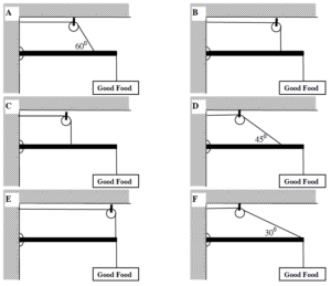
Rank the design scenarios on the basis of the tension in the supporting cable.
Largest 1. _____ 2. _____ 3. _____ 4. _____ 5. _____ 6. _____ Smallest
_____ The ranking cannot be determined based on the information provided.
Explain the reason for your ranking:
Two identical, uniform, solid spheres are attached together by a solid, uniform thin rod. The rod lies on a line connecting the centers-of-mass of the two spheres. The axes A, B, C, and D are in the plane of the page (which contains the centers-of-mass of the spheres and the rod), while axes E and F are perpendicular to the page.
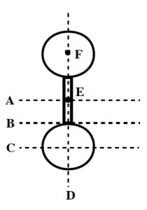
Rank the rotational inertia of this object about the axes indicated.
Largest 1. _____ 2. _____ 3. _____ 4. _____ 5. _____ 6. _____ Smallest
_____ The ranking cannot be determined based on the information provided.
Explain the reason for your ranking:
Below are top views of six identical turntables, upon which are fastened different masses. The distance from the center of the turntable to the center of the mass is either zero, one-half the radius of the turntable, or the radius of the turntable.
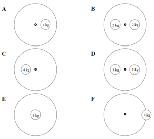
Rank the rotational inertia of these turntable-mass systems.
Largest 1. _____ 2. _____ 3. _____ 4. _____ 5. _____ 6. _____ Smallest
_____ The ranking cannot be determined based on the information provided.
Explain the reason for your ranking:
Below are top views of six identical turntables, upon which are fastened different masses. The distance from the center of the turntable to the center of the mass is either zero, one-half the radius of the turntable, or the radius of the turntable.
Rank the rotational inertia of these turntable-mass systems.
Largest 1. _____ 2. _____ 3. _____ 4. _____ 5. _____ 6. _____ Smallest
_____ The ranking cannot be determined based on the information provided.
Explain the reason for your ranking:
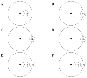
A block of mass M is attached to the inner radius (Rinner) of the pulley shown below. A second rope is attached to outer radius (Router) of the pulley. Assume friction in the pulley mount is very small.
Rank these scenarios on the basis of the magnitude of the force that must be applied to the free rope to hold the block stationary.
Largest 1. _____ 2. _____ 3. _____ 4. _____ 5. _____ 6. _____ Smallest
_____ The ranking cannot be determined based on the information provided.
Explain the reason for your ranking:
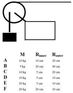
A 10 kg block is attached to the inner radius (Rinner) of the pulley shown below. A second rope, attached to outer radius (Router) of the pulley, is used to raise the block at constant speed v. Assume friction in the pulley mount is very small.
Rank these scenarios on the basis of the magnitude of the force that must be applied to the free rope to raise the block at the speed indicated.
Largest 1. _____ 2. _____ 3. _____ 4. _____ 5. _____ 6. _____ Smallest
_____ The ranking cannot be determined based on the information provided.
Explain the reason for your ranking:
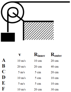
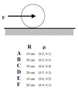
A disk of mass m is pushed along a level surface by a force acting at its center-of-mass. The disk begins at rest and rolls without slipping along the surface. The coefficient of friction between the disk and the surface, m, is listed below. All disks are pushed by the same magnitude force and have the same radius.
Rank the disks on the magnitude of the frictional force acting on them.
Largest 1. _____ 2. _____ 3. _____ 4. _____ 5. _____ 6. _____ Smallest
_____ The ranking cannot be determined based on the information provided.
Explain the reason for your ranking:
Rank the disks on the magnitude of their acceleration.
Largest 1. _____ 2. _____ 3. _____ 4. _____ 5. _____ 6. _____ Smallest
_____ The ranking cannot be determined based on the information provided.
Explain the reason for your ranking:
A sphere of radius R is pushed along a level surface by a force acting at its center-of-mass. The sphere begins at rest and rolls without slipping along the surface. The coefficient of friction between the sphere and the surface, m, is listed below. All spheres are pushed by the same magnitude force and have the same mass.
Rank the spheres on the magnitude of the frictional force acting on them.
Largest 1. _____ 2. _____ 3. _____ 4. _____ 5. _____ 6. _____ Smallest
_____ The ranking cannot be determined based on the information provided.
Explain the reason for your ranking:
Rank the spheres on the magnitude of their acceleration.
Largest 1. _____ 2. _____ 3. _____ 4. _____ 5. _____ 6. _____ Smallest
_____ The ranking cannot be determined based on the information provided.
Explain the reason for your ranking:
A hollow sphere is pushed along a level surface by a force, F, acting at its center-of-mass. The hollow sphere begins at rest and rolls without slipping along the surface. The coefficient of friction between the hollow sphere and the surface, m, is listed below. All hollow spheres have the same mass and radius.
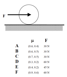
Rank the hollow spheres on the magnitude of the frictional force acting on them.
Largest 1. _____ 2. _____ 3. _____ 4. _____ 5. _____ 6. _____ Smallest
_____ The ranking cannot be determined based on the information provided.
Explain the reason for your ranking:
Rank the hollow spheres on the magnitude of their acceleration.
Largest 1. _____ 2. _____ 3. _____ 4. _____ 5. _____ 6. _____ Smallest
_____ The ranking cannot be determined based on the information provided.
Explain the reason for your ranking:
A disk of mass m is released from rest from the top of an incline. The disk rolls without slipping down the incline. The coefficient of friction between the disk and the incline, m, is listed below. All disks are released from the same point on the incline and have the same radius.
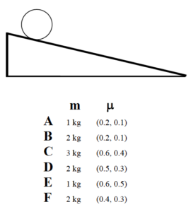
Rank the disks on their speed at the bottom of the incline.
Largest 1. _____ 2. _____ 3. _____ 4. _____ 5. _____ 6. _____ Smallest
_____ The ranking cannot be determined based on the information provided.
Explain the reason for your ranking:
Rank the disks on the magnitude of the frictional force acting on them.
Largest 1. _____ 2. _____ 3. _____ 4. _____ 5. _____ 6. _____ Smallest
_____ The ranking cannot be determined based on the information provided.
Explain the reason for your ranking:
| The roadside sign at right has a mass of 22 kg. It hangs from the end of a 1.6 m long, 14 kg support pole hinged to the wall. A support cable is attached to the pole 1.1 m from the wall. | 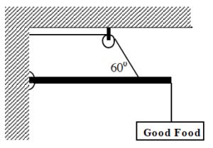 |
Free-Body Diagram Mathematical Analysis[i]
| The roadside sign at right has a mass of 22 kg. It hangs from a 1.6 m long, 14 kg support pole hinged to the wall. A support cable is attached to the pole at both 0.4 m and 1.2 m from the wall. The sign is hung directly below the outer support cable. | 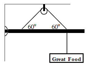 |
Free-Body Diagram Mathematical Analysis[ii]
| The roadside sign at right has a mass of 22 kg. It hangs from the end of a 1.6 m long, 14 kg support pole hinged to the wall at an angle of 250 above horizontal. A support cable is attached to the pole at a point 1.1 m from the wall along the pole. |  |
Free-Body Diagram Mathematical Analysis[iii]
| The 70 kg strange man has built a simple scaffold by placing a 6 m long, 35 kg board on top of two piles of bricks. The brick supports are 2 m apart and centered on the CM of the board. The man’s 10 kg toolbox is 1 m from the right edge of the board. The man is 1.1 m from the left edge of the board when he stops and realizes he probably can’t walk all the way to the left edge of the board. | 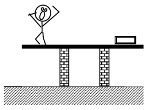 |
Free-Body Diagram Mathematical Analysis[iv]
| The two 70 kg strange twins have built a simple scaffold by placing a 6 m long, 35 kg board on top of two piles of bricks. The brick supports are 2 m apart and centered on the CM of the board. One twin is at the extreme right edge of the board while the other is 1.2 m from the left edge. | 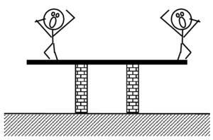 |
Free-Body Diagram Mathematical Analysis[v]
| The 70 kg strange man has climbed three-quarters of the way up the 20 kg, 10 m long ladder when he stops and realizes that 50° may not be a very safe angle for a ladder. The coefficient of friction between the base of the ladder and the ground is (0.6, 0.5). The friction between the ladder and the wall is negligible. | 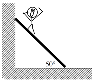 |
Free-Body Diagram Mathematical Analysis[vi]
| The 75 kg man is falling at 20 m/s, 75 m above the crocodile-infested waters below! In an attempt to save him, the brake shoe is pressed against the spinning pulley. The coefficient of friction between the brake shoe and the pulley is (0.9, 0.8), and the 35 kg disk-shaped pulley has inner and outer diameters of 0.60 m and 0.90 m, respectively. | 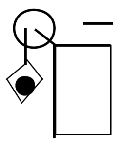 |
Motion Information Free-Body Diagrams
| Object:
Event 1:
t1 =
r1 = q1 =
v1 = w1 =
a1 = a1 = |
Event 2:
t2 =
r2 = q2 =
v2 = w2 =
a2 = a2 = |
Mathematical Analysis[vii]
Tired of walking up the stairs, an 80 kg engineering student designs an ingenious device for reaching his third floor dorm room. An 84 kg block is attached to a rope that passes over a 0.7 m diameter, 15 kg, disk-shaped pulley. The student holds the other end of the rope. When the 84 kg block is released, the student is pulled up to his dorm room, 8 m off the ground.
Motion Information Free-Body Diagrams
| Object:
Event 1:
t1 =
r1 = q1 =
v1 = w1 =
a1 = a1 = |
Event 2:
t2 =
r2 = q2 =
v2 = w2 =
a2 = a2 = |
Mathematical Analysis[viii]
Tired of walking up the stairs, an 80 kg engineering student designs an ingenious device for reaching her third floor dorm room. An 42 kg block is attached to a rope that passes over the outer diameter of a 0.7 m outer diameter, 15 kg, disk-shaped compound pulley. The student holds a second rope, wrapped around the inner 0.35 m diameter of the pulley. When the 42 kg block is released, the student is pulled up to her dorm room, 8 m off the ground.
Motion Information Free-Body Diagrams
| Object:
Event 1:
t1 =
r1 = q1 =
v1 = w1 =
a1 = a1 = |
Event 2:
t2 =
r2 = q2 =
v2 = w2 =
a2 = a2 = |
Mathematical Analysis[ix]
| A 60 kg student lifts herself from rest to a speed of 1.5 m/s in 2.1 s. The boson’s chair has a mass of 35 kg. The 20 kg, disk-shaped pulley has a diameter of 1.1 m. |  |
Motion Information Free-Body Diagrams
| Object:
Event 1:
t1 =
r1 = q1 =
v1 = w1 =
a1 = a1 = |
Event 2:
t2 =
r2 = q2 =
v2 = w2 =
a2 = a2 = |
Mathematical Analysis[x]
| The device at right guarantees all the excitement of skiing without the need for hills. The 80 kg man begins from rest and reaches a speed of 34 m/s in 7.2 s. The 10 kg, disk-shaped pulley has inner and outer diameters of 0.40 m and 0.90 m, respectively. Assume friction is so small that it can be ignored. | 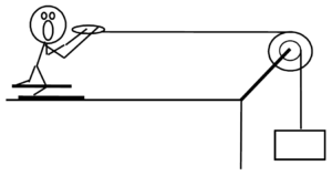 |
Motion Information Free-Body Diagrams
| Object:
Event 1:
t1 =
r1 = q1 =
v1 = w1 =
a1 = a1 = |
Event 2:
t2 =
r2 = q2 =
v2 = w2 =
a2 = a2 = |
Mathematical Analysis[xi]
| The device at right allows you to ski uphill. The ballast block has a mass of 30 kg and the skier has a mass of 70 kg. The 10 kg, disk-shaped pulley has diameter 0.90 m. Assume friction is so small that it can be ignored. The ramp is 45 m long and inclined at 200 above horizontal. | 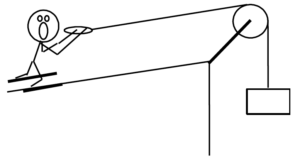 |
Motion Information Free-Body Diagrams
| Object:
Event 1:
t1 =
r1 = q1 =
v1 = w1 =
a1 = a1 = |
Event 2:
t2 =
r2 = q2 =
v2 = w2 =
a2 = a2 = |
Mathematical Analysis[xii]
A yo-yo of mass 0.60 kg, inner diameter 0.70 cm, and outer diameter 8.0 cm is released from rest. The string is 0.80 m long. Assume the rotational inertia of the yo-yo is similar to a simple disk and that the unwinding of the string does not effect the rotational inertia.
Motion Information Free-Body Diagram
| Event 1:
t1 =
r1 = q1 =
v1 = w1 =
a1 = a1 = |
Event 2:
t2 =
r2 = q2 =
v2 = w2 =
a2 = a2 = |
Mathematical Analysis[xiii]
A bowling ball of mass 7.1 kg and diameter 21.6 cm is thrown down the alley at a speed of 8.7 m/s. The bowling ball is initially skidding, with no angular velocity, down the alley. The coefficient of friction between the ball and the alley is (0.30, 0.25).
Motion Information Free-Body Diagram
| Event 1:
t1 =
r1 = q1 =
v1 = w1 =
a1 = a1 = |
Event 2:
t2 =
r2 = q2 =
v2 = w2 =
a2 = a2 = |
Mathematical Analysis[xiv]
A bowling ball of mass 7.1 kg and diameter 21.6 cm is thrown down the alley at a speed of 9.5 m/s. The bowling ball is initially skidding, with no angular velocity, down the alley. The ball travels 9.6 m before it begins to roll without slipping.
Motion Information Free-Body Diagram
| Event 1:
t1 =
r1 = q1 =
v1 = w1 =
a1 = a1 = |
Event 2:
t2 =
r2 = q2 =
v2 = w2 =
a2 = a2 = |
Mathematical Analysis[xv]
| The strange man at right is pretending to be a steamroller by pushing a heavy cylindrical object around his backyard. The cylinder has a mass of 50 kg and a diameter of 0.70 m. The man pushes with a force of 400 N at an angle of 180 below horizontal. The coefficient of friction between the cylinder and the ground is (0.6, 0.4). | 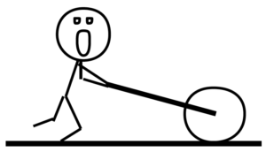 |
Free-Body Diagram Mathematical Analysis[xvi]
| The 65 kg man at right is trapped inside a section of large pipe. If that’s not bad enough, the pipe begins to roll, from rest, down a 35 m long, 180 incline! The pipe has a mass of 180 kg and a diameter of 1.2 m. (Assume the man’s presence inside the pipe has a negligible effect on the pipe’s rotational inertia.) The coefficient of friction between the pipe and the ground is (0.5, 0.4). | 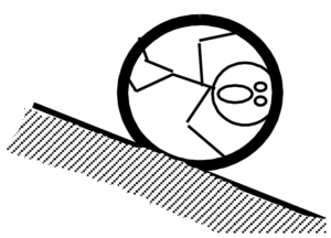 |
Motion Information Free-Body Diagram
| Event 1:
t1 =
r1 = q1 =
v1 = w1 =
a1 = a1 = |
Event 2:
t2 =
r2 = q2 =
v2 = w2 =
a2 = a2 = |
Mathematical Analysis[xvii]
| The roadside sign at right has mass M. It hangs from the end of a support pole of length L and mass m, hinged to the wall at an angle of q above horizontal. A support cable is attached vertically to the pole at its midpoint. Determine the force exerted by the cable on the pole (Fcable) as a function of M, m, g, L, and q. | 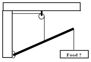 |
Free-Body Diagram Mathematical Analysis
Questions
If M = 0 kg, what should Fcable equal? Does your function agree with this observation?
If the length of the pole was doubled, what would happen to Fcable?
| Determine the minimum angle (qmin) with which the ladder can be leaned against the wall and not slip as a function of the ladder’s mass (m), length (L), g, and the appropriate coefficient of friction. Assume the friction between the ladder and the wall is negligible. |  |
Free-Body Diagram Mathematical Analysis
Questions
If m = 0, what should qmin equal? Does your function agree with this observation?
If the mass of the ladder was doubled, what would happen to qmin?
| Determine the minimum coefficient of static friction (mmin) needed for the ladder not to slip as a function of the ladder’s mass (m) and length (L), the man’s mass (M) and position along the ladder (d), g, and the angle the ladder makes with the floor (q). Assume the friction between the ladder and the wall is negligible. |  |
Free-Body Diagram Mathematical Analysis
Questions
If q = 90°, what should mmin equal? Does your function agree with this observation?
Tired of walking up the stairs, an engineering student of mass m designs an ingenious device for reaching her third floor dorm room. An block of mass M is attached to a rope that passes over the outer diameter, D, of a disk-shaped compound pulley of mass Mp. The student holds a second rope, wrapped around the inner diameter, d, of the pulley. When the block is released, the student is pulled up to her dorm room. Determine the acceleration of the student (as) as a function of m, M, Mp, d, D, and g.
Free-Body Diagrams Mathematical Analysis
Questions
If Mp = ∞, what should as equal? Does your function agree with this observation?
If d = D and m = M, what should as equal? Does your function agree with this observation?
If md > MD, what should as equal? Does your function agree with this observation?
| The strange man at right is pretending to be a steamroller by pushing a heavy cylindrical object around his backyard. The cylinder has a mass, M, and a diameter, D. The man pushes at an angle of q below horizontal. Determine the maximum force (Fmax) with which the man can push and the “steamroller” roll without slipping as a function of M, D, g, q, and the appropriate coefficient of friction between the cylinder and the ground. | 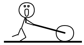 |
Free-Body Diagram Mathematical Analysis
Questions
If m = 0, what should Fmax equal? Does your function agree with this observation?
Above what angle can the man push as hard as he can and still have the steamroller roll without slipping?
| A man of mass m is trapped inside a pipe of mass M and diameter D initially at rest on an incline of angle q. Determine the minimum angle (qmin) above which the pipe will slide down the incline as a function of m, M, D, g, and the appropriate coefficient of friction between the pipe and the ground. Assume the man’s presence inside the pipe has a negligible effect on the pipe’s rotational inertia. | 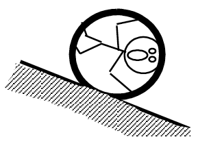 |
Free-Body Diagram Mathematical Analysis
Questions
If m = 0, what should qmin equal? Does your function agree with this observation?
[i] F rope = 477 N
[ii] F rope = 266 N
[iii] F rope = 375 N
[iv] Frightsupport = 9.8 N Fleftsupport = 1117 N
[v] Frightsupport = 1269 N Fleftsupport = 446 N
[vi] Fsf = 514 N
[vii] F minimum = 867 N
[viii] a student = 0.23 m/s2
[ix] a student = 0.14 m/s2
[x] F right rope = 503 N
[xi] m block = 117 kg
[xii] a skier = 0.57 m/s2
[xiii] a = 0.15 m/s2
[xiv] t2 = 1.01 s
[xv] t2 = 1.18 s
[xvi] a = 5.07 m/s2
[xvii] a = 1.75 m/s2
Homework 11 – Model 4: 62, 65, 67, 72, 77, 79, 83, 94, 95, 98.
