
35 DC Circuits Containing Resistors and Capacitors
Learning Objectives
By the end of this section, you will be able to:
- Explain the importance of the time constant, τ, and calculate the time constant for a given resistance and capacitance.
- Explain why batteries in a flashlight gradually lose power and the light dims over time.
- Describe what happens to a graph of the voltage across a capacitor over time as it charges.
- Explain how a timing circuit works and list some applications.
- Calculate the necessary speed of a strobe flash needed to “stop” the movement of an object over a particular length.
When you use a flash camera, it takes a few seconds to charge the capacitor that powers the flash. The light flash discharges the capacitor in a tiny fraction of a second. Why does charging take longer than discharging? This question and a number of other phenomena that involve charging and discharging capacitors are discussed in this module.
RC Circuits
An RC circuit is one containing a resistor R and a capacitor C. The capacitor is an electrical component that stores electric charge.
Figure 1 shows a simple RC circuit that employs a DC (direct current) voltage source. The capacitor is initially uncharged. As soon as the switch is closed, current flows to and from the initially uncharged capacitor. As charge increases on the capacitor plates, there is increasing opposition to the flow of charge by the repulsion of like charges on each plate.
In terms of voltage, this is because voltage across the capacitor is given by Vc = Q/C, where Q is the amount of charge stored on each plate and C is the capacitance. This voltage opposes the battery, growing from zero to the maximum emf when fully charged. The current thus decreases from its initial value of [latex]I_{o}=\frac{\text{emf}}{R}\\[/latex] to zero as the voltage on the capacitor reaches the same value as the emf. When there is no current, there is no IR drop, and so the voltage on the capacitor must then equal the emf of the voltage source. This can also be explained with Kirchhoff’s second rule (the loop rule), discussed in Kirchhoff’s Rules, which says that the algebraic sum of changes in potential around any closed loop must be zero.
The initial current is [latex]I_{o} =\frac{\text{emf}}{R}\\[/latex], because all of the IR drop is in the resistance. Therefore, the smaller the resistance, the faster a given capacitor will be charged. Note that the internal resistance of the voltage source is included in R, as are the resistances of the capacitor and the connecting wires. In the flash camera scenario above, when the batteries powering the camera begin to wear out, their internal resistance rises, reducing the current and lengthening the time it takes to get ready for the next flash.
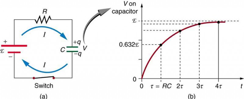
Voltage on the capacitor is initially zero and rises rapidly at first, since the initial current is a maximum. Figure 1(b) shows a graph of capacitor voltage versus time (t) starting when the switch is closed at t = 0. The voltage approaches emf asymptotically, since the closer it gets to emf the less current flows. The equation for voltage versus time when charging a capacitor C through a resistor R, derived using calculus, is
V = emf(1 − e−t/RC) (charging),
where V is the voltage across the capacitor, emf is equal to the emf of the DC voltage source, and the exponential e = 2.718 … is the base of the natural logarithm. Note that the units of RC are seconds. We define
τ = RC
where τ (the Greek letter tau) is called the time constant for an RC circuit. As noted before, a small resistance R allows the capacitor to charge faster. This is reasonable, since a larger current flows through a smaller resistance. It is also reasonable that the smaller the capacitor C, the less time needed to charge it. Both factors are contained in τ = RC. More quantitatively, consider what happens when t = τ = RC. Then the voltage on the capacitor is
V = emf (1 − e−1) = emf (1 − 0.368) = 0.632 ⋅ emf.
This means that in the time τ = RC, the voltage rises to 0.632 of its final value. The voltage will rise 0.632 of the remainder in the next time τ. It is a characteristic of the exponential function that the final value is never reached, but 0.632 of the remainder to that value is achieved in every time, τ. In just a few multiples of the time constant τ, then, the final value is very nearly achieved, as the graph in Figure 1(b) illustrates.
Discharging a Capacitor
Discharging a capacitor through a resistor proceeds in a similar fashion, as Figure 2 illustrates. Initially, the current is [latex]{I}_{0}=\frac{{V}_{0}}{R}\\[/latex], driven by the initial voltage V0 on the capacitor. As the voltage decreases, the current and hence the rate of discharge decreases, implying another exponential formula for V. Using calculus, the voltage V on a capacitor C being discharged through a resistor R is found to be
V = V0e−t/RC(discharging).
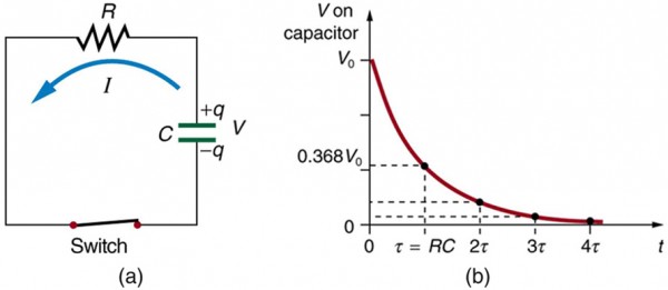
The graph in Figure 2(b) is an example of this exponential decay. Again, the time constant is τ = RC. A small resistance R allows the capacitor to discharge in a small time, since the current is larger. Similarly, a small capacitance requires less time to discharge, since less charge is stored. In the first time interval τ = RC after the switch is closed, the voltage falls to 0.368 of its initial value, since V = V0 ⋅ e−1 = 0.368V0.
During each successive time τ, the voltage falls to 0.368 of its preceding value. In a few multiples of τ, the voltage becomes very close to zero, as indicated by the graph in Figure 2(b). Now we can explain why the flash camera in our scenario takes so much longer to charge than discharge; the resistance while charging is significantly greater than while discharging. The internal resistance of the battery accounts for most of the resistance while charging. As the battery ages, the increasing internal resistance makes the charging process even slower. (You may have noticed this.)
The flash discharge is through a low-resistance ionized gas in the flash tube and proceeds very rapidly. Flash photographs, such as in Figure 3, can capture a brief instant of a rapid motion because the flash can be less than a microsecond in duration. Such flashes can be made extremely intense. During World War II, nighttime reconnaissance photographs were made from the air with a single flash illuminating more than a square kilometer of enemy territory. The brevity of the flash eliminated blurring due to the surveillance aircraft’s motion. Today, an important use of intense flash lamps is to pump energy into a laser. The short intense flash can rapidly energize a laser and allow it to reemit the energy in another form.

Example 1. Integrated Concept Problem: Calculating Capacitor Size—Strobe Lights
High-speed flash photography was pioneered by Doc Edgerton in the 1930s, while he was a professor of electrical engineering at MIT. You might have seen examples of his work in the amazing shots of hummingbirds in motion, a drop of milk splattering on a table, or a bullet penetrating an apple (see Figure 3). To stop the motion and capture these pictures, one needs a high-intensity, very short pulsed flash, as mentioned earlier in this module.
Suppose one wished to capture the picture of a bullet (moving at 5.0 × 10² m/s) that was passing through an apple. The duration of the flash is related to the RC time constant, τ. What size capacitor would one need in the RC circuit to succeed, if the resistance of the flash tube was 10.0 Ω? Assume the apple is a sphere with a diameter of 8.0 × 10⁻²m.
Strategy
We begin by identifying the physical principles involved. This example deals with the strobe light, as discussed above. Figure 2 shows the circuit for this probe. The characteristic time τ of the strobe is given as τ = RC.
Solution
We wish to find C, but we don’t know τ. We want the flash to be on only while the bullet traverses the apple. So we need to use the kinematic equations that describe the relationship between distance x, velocity v, and time t:
x = vt or [latex]t=\frac{x}{v}\\[/latex].
The bullet’s velocity is given as 5.0 × 10² m/s, and the distance x is 8.0 × 10⁻² m The traverse time, then, is
[latex]t=\frac{x}{v}=\frac{8.0\times {10}^{-2}\text{ m}}{5.0\times {10}^{2}\text{ m/s}}=1.6\times {\text{10}}^{-4}\text{ s}\\[/latex].
We set this value for the crossing time t equal to τ. Therefore,
[latex]C=\frac{t}{R}=\frac{1.6\times \text{10}^{-4}\text{ s}}{10.0\text{ }\Omega }=16\text{ }\mu\text{ F}\\[/latex].
(Note: Capacitance C is typically measured in farads, F, defined as Coulombs per volt. From the equation, we see that C can also be stated in units of seconds per ohm.)
Discussion
The flash interval of 160 μs (the traverse time of the bullet) is relatively easy to obtain today. Strobe lights have opened up new worlds from science to entertainment. The information from the picture of the apple and bullet was used in the Warren Commission Report on the assassination of President John F. Kennedy in 1963 to confirm that only one bullet was fired.
RC Circuits for Timing
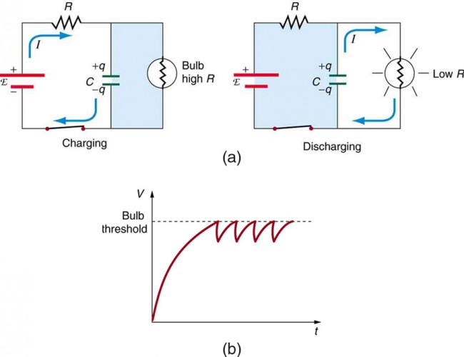
RC circuits are commonly used for timing purposes. A mundane example of this is found in the ubiquitous intermittent wiper systems of modern cars. The time between wipes is varied by adjusting the resistance in an RC circuit. Another example of an RC circuit is found in novelty jewelry, Halloween costumes, and various toys that have battery-powered flashing lights. (See Figure 4 for a timing circuit.)
A more crucial use of RC circuits for timing purposes is in the artificial pacemaker, used to control heart rate. The heart rate is normally controlled by electrical signals generated by the sino-atrial (SA) node, which is on the wall of the right atrium chamber. This causes the muscles to contract and pump blood. Sometimes the heart rhythm is abnormal and the heartbeat is too high or too low. The artificial pacemaker is inserted near the heart to provide electrical signals to the heart when needed with the appropriate time constant. Pacemakers have sensors that detect body motion and breathing to increase the heart rate during exercise to meet the body’s increased needs for blood and oxygen.
Example 2. Calculating Time: RC Circuit in a Heart Defibrillator
A heart defibrillator is used to resuscitate an accident victim by discharging a capacitor through the trunk of her body. A simplified version of the circuit is seen in Figure 2. (a) What is the time constant if an 8.00-μF capacitor is used and the path resistance through her body is 1.00 × 10³ Ω? (b) If the initial voltage is 10.0 kV, how long does it take to decline to 5.00 × 10² V?
Strategy
Since the resistance and capacitance are given, it is straightforward to multiply them to give the time constant asked for in part (a). To find the time for the voltage to decline to 5.00 × 10² V, we repeatedly multiply the initial voltage by 0.368 until a voltage less than or equal to 5.00 × 10² V is obtained. Each multiplication corresponds to a time of τ seconds.
Solution for (a)
The time constant τ is given by the equation τ = RC. Entering the given values for resistance and capacitance (and remembering that units for a farad can be expressed as s/Ω) gives
τ = RC = (1.00 × 10³ Ω) (8.00 μF) = 8.00 ms.
Solution for (b)
In the first 8.00 ms, the voltage (10.0 kV) declines to 0.368 of its initial value. That is:
(Notice that we carry an extra digit for each intermediate calculation.) After another 8.00 ms, we multiply by 0.368 again, and the voltage is
[latex]\begin{array}{lll}V′ & =& 0.368\text{ V}\\ & =& \left(0.368\right)\left(3.680\times {10}^{3}\text{ V}\right)\\ & =& 1.354\times {10}^{3}\text{ V}\text{at }t=16.0\text{ ms}\end{array}\\[/latex]
Similarly, after another 8.00 ms, the voltage is
[latex]\begin{array}{lll}V'' & =& 0.368\text{ }V' =\left(\text{0.368}\right)\left(\text{1.354}\times{10}^{3}\text{ V}\right)\\ & =& 498\text{ V at }t=24.0\text{ ms}\end{array}\\[/latex].
Discussion
So after only 24.0 ms, the voltage is down to 498 V, or 4.98% of its original value.Such brief times are useful in heart defibrillation, because the brief but intense current causes a brief but effective contraction of the heart. The actual circuit in a heart defibrillator is slightly more complex than the one in Figure 2, to compensate for magnetic and AC effects that will be covered in Magnetism.
Check Your Understanding
Solution
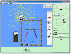
PhET Explorations: Circuit Construction Kit (DC only)
Section Summary
- An RC circuit is one that has both a resistor and a capacitor.
- The time constant τ for an RC circuit is τ = RC.
- When an initially uncharged (V0 = 0 at t = 0) capacitor in series with a resistor is charged by a DC voltage source, the voltage rises, asymptotically approaching the emf of the voltage source; as a function of time,
- Within the span of each time constant τ, the voltage rises by 0.632 of the remaining value, approaching the final voltage asymptotically.
- If a capacitor with an initial voltage V0 is discharged through a resistor starting att = 0, then its voltage decreases exponentially as given by
V = V0e−t/RC(discharging).
- In each time constant τ, the voltage falls by 0.368 of its remaining initial value, approaching zero asymptotically.
Conceptual questions
1. Regarding the units involved in the relationship τ = RC, verify that the units of resistance times capacitance are time, that is, Ω ⋅ F=s.
2. The RC time constant in heart defibrillation is crucial to limiting the time the current flows. If the capacitance in the defibrillation unit is fixed, how would you manipulate resistance in the circuit to adjust the RC constant τ? Would an adjustment of the applied voltage also be needed to ensure that the current delivered has an appropriate value?
3. When making an ECG measurement, it is important to measure voltage variations over small time intervals. The time is limited by the RC constant of the circuit—it is not possible to measure time variations shorter than RC. How would you manipulate R and C in the circuit to allow the necessary measurements?
4. Draw two graphs of charge versus time on a capacitor. Draw one for charging an initially uncharged capacitor in series with a resistor, as in the circuit in Figure 1 (above), starting from t = 0. Draw the other for discharging a capacitor through a resistor, as in the circuit in Figure 2 (above), starting at t = 0, with an initial charge Qo. Show at least two intervals of τ.
5. When charging a capacitor, as discussed in conjunction with Figure 2, how long does it take for the voltage on the capacitor to reach emf? Is this a problem?
6. When discharging a capacitor, as discussed in conjunction with Figure 2, how long does it take for the voltage on the capacitor to reach zero? Is this a problem?
7. Referring to Figure 1, draw a graph of potential difference across the resistor versus time, showing at least two intervals of τ. Also draw a graph of current versus time for this situation.
8. A long, inexpensive extension cord is connected from inside the house to a refrigerator outside. The refrigerator doesn’t run as it should. What might be the problem?
9. In Figure 4 (above), does the graph indicate the time constant is shorter for discharging than for charging? Would you expect ionized gas to have low resistance? How would you adjust R to get a longer time between flashes? Would adjusting R affect the discharge time?
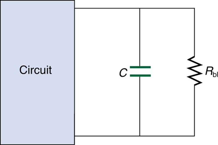
10. An electronic apparatus may have large capacitors at high voltage in the power supply section, presenting a shock hazard even when the apparatus is switched off. A “bleeder resistor” is therefore placed across such a capacitor, as shown schematically in Figure 6, to bleed the charge from it after the apparatus is off. Why must the bleeder resistance be much greater than the effective resistance of the rest of the circuit? How does this affect the time constant for discharging the capacitor?
Problems & Exercises
1. The timing device in an automobile’s intermittent wiper system is based on an RC time constant and utilizes a 0.500-μF capacitor and a variable resistor. Over what range must R be made to vary to achieve time constants from 2.00 to 15.0 s?
2. A heart pacemaker fires 72 times a minute, each time a 25.0-nF capacitor is charged (by a battery in series with a resistor) to 0.632 of its full voltage. What is the value of the resistance?
3. The duration of a photographic flash is related to an RC time constant, which is 0.100 μs for a certain camera. (a) If the resistance of the flash lamp is 0.0400 Ω during discharge, what is the size of the capacitor supplying its energy? (b) What is the time constant for charging the capacitor, if the charging resistance is 800 kΩ?
4. A 2.00- and a 7.50-μF capacitor can be connected in series or parallel, as can a 25.0- and a 100-kΩ resistor. Calculate the four RC time constants possible from connecting the resulting capacitance and resistance in series.
5. After two time constants, what percentage of the final voltage, emf, is on an initially uncharged capacitor C, charged through a resistance R?
6. A 500-Ω resistor, an uncharged 1.50-μF capacitor, and a 6.16-V emf are connected in series. (a) What is the initial current? (b) What is the RC time constant? (c) What is the current after one time constant? (d) What is the voltage on the capacitor after one time constant?
7. A heart defibrillator being used on a patient has an RC time constant of 10.0 ms due to the resistance of the patient and the capacitance of the defibrillator. (a) If the defibrillator has an 8.00-μF capacitance, what is the resistance of the path through the patient? (You may neglect the capacitance of the patient and the resistance of the defibrillator.) (b) If the initial voltage is 12.0 kV, how long does it take to decline to 6.00 × 10² V?
8. An ECG monitor must have an RC time constant less than 1.00 × 10² μs to be able to measure variations in voltage over small time intervals. (a) If the resistance of the circuit (due mostly to that of the patient’s chest) is 1.00 kΩ, what is the maximum capacitance of the circuit? (b) Would it be difficult in practice to limit the capacitance to less than the value found in (a)?
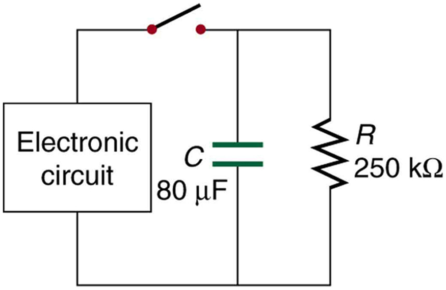
9. Figure 7 shows how a bleeder resistor is used to discharge a capacitor after an electronic device is shut off, allowing a person to work on the electronics with less risk of shock. (a) What is the time constant? (b) How long will it take to reduce the voltage on the capacitor to 0.250% (5% of 5%) of its full value once discharge begins? (c) If the capacitor is charged to a voltage V0 through a 100-Ω resistance, calculate the time it takes to rise to 0.865 V0 (This is about two time constants.)
10. Using the exact exponential treatment, find how much time is required to discharge a 250-μF capacitor through a 500-Ω resistor down to 1.00% of its original voltage.
11. Using the exact exponential treatment, find how much time is required to charge an initially uncharged 100-pF capacitor through a 75.0-MΩ resistor to 90.0% of its final voltage.
12. Integrated Concepts If you wish to take a picture of a bullet traveling at 500 m/s, then a very brief flash of light produced by an RC discharge through a flash tube can limit blurring. Assuming 1.00 mm of motion during one RC constant is acceptable, and given that the flash is driven by a 600-μF capacitor, what is the resistance in the flash tube?
13. Integrated Concepts A flashing lamp in a Christmas earring is based on an RC discharge of a capacitor through its resistance. The effective duration of the flash is 0.250 s, during which it produces an average 0.500 W from an average 3.00 V. (a) What energy does it dissipate? (b) How much charge moves through the lamp? (c) Find the capacitance. (d) What is the resistance of the lamp?
14. Integrated Concepts A 160-μF capacitor charged to 450 V is discharged through a 31.2-kΩ resistor. (a) Find the time constant. (b) Calculate the temperature increase of the resistor, given that its mass is 2.50 g and its specific heat is[latex]1.67\frac{\text{kJ}}{\text{kg}\cdotº\text{C}}\\[/latex], noting that most of the thermal energy is retained in the short time of the discharge. (c) Calculate the new resistance, assuming it is pure carbon. (d) Does this change in resistance seem significant?
15. Unreasonable Results (a) Calculate the capacitance needed to get an RC time constant of 1.00 × 10³ with a 0.100-Ω resistor. (b) What is unreasonable about this result? (c) Which assumptions are responsible?
16. Construct Your Own Problem Consider a camera’s flash unit. Construct a problem in which you calculate the size of the capacitor that stores energy for the flash lamp. Among the things to be considered are the voltage applied to the capacitor, the energy needed in the flash and the associated charge needed on the capacitor, the resistance of the flash lamp during discharge, and the desired RC time constant.
17. Construct Your Own Problem Consider a rechargeable lithium cell that is to be used to power a camcorder. Construct a problem in which you calculate the internal resistance of the cell during normal operation. Also, calculate the minimum voltage output of a battery charger to be used to recharge your lithium cell. Among the things to be considered are the emf and useful terminal voltage of a lithium cell and the current it should be able to supply to a camcorder.
Glossary
- RC circuit:
- a circuit that contains both a resistor and a capacitor
- capacitor:
- an electrical component used to store energy by separating electric charge on two opposing plates
- capacitance:
- the maximum amount of electric potential energy that can be stored (or separated) for a given electric potential
Selected Solutions to Problems & Exercises
1. range 4.00 to 30.0 MΩ
3. (a) 2.50 μF (b) 2.00 s
5. 86.5%
7. (a) 1.25 kΩ (b) 30.0 ms
9. (a) 20.0 s (b) 120 s (c) 16.0 ms
11. 1.73 × 10⁻² s
12. 3.33 × 10⁻³ Ω
14. (a) 4.99 s (b) 3.87ºC (c) 31.1 kΩ (d) No
