
52 Magnetic Force between Two Parallel Conductors
Learning Objectives
By the end of this section, you will be able to:
- Describe the effects of the magnetic force between two conductors.
- Calculate the force between two parallel conductors.
You might expect that there are significant forces between current-carrying wires, since ordinary currents produce significant magnetic fields and these fields exert significant forces on ordinary currents. But you might not expect that the force between wires is used to define the ampere. It might also surprise you to learn that this force has something to do with why large circuit breakers burn up when they attempt to interrupt large currents.
The force between two long straight and parallel conductors separated by a distance r can be found by applying what we have developed in preceding sections. Figure 1 shows the wires, their currents, the fields they create, and the subsequent forces they exert on one another. Let us consider the field produced by wire 1 and the force it exerts on wire 2 (call the force F2). The field due to I1 at a distance r is given to be
[latex]{B}_{1}=\frac{\mu_{0}{I}_{1}}{2\pi r}\\[/latex].
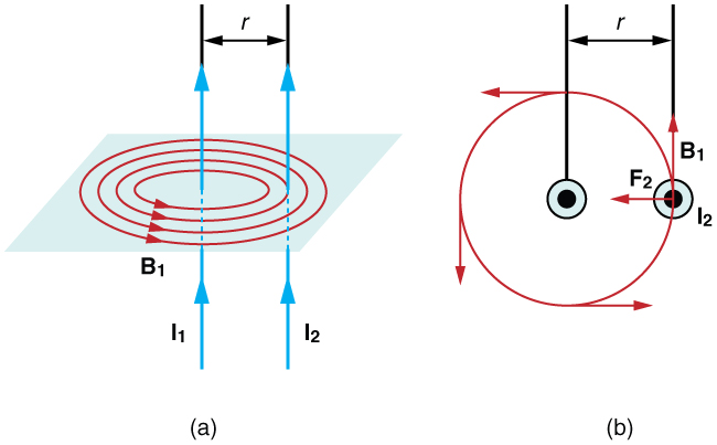
This field is uniform along wire 2 and perpendicular to it, and so the force F2 it exerts on wire 2 is given by [latex]F=IlB\sin\theta\\[/latex] with [latex]\sin\theta =1\\[/latex]:
[latex]{F}_{2}={I}_{2}{\text{lB}}_{1}\\[/latex].
By Newton’s third law, the forces on the wires are equal in magnitude, and so we just write F for the magnitude of F2. (Note that F1=−F2.) Since the wires are very long, it is convenient to think in terms of F/l, the force per unit length. Substituting the expression for B1 into the last equation and rearranging terms gives
[latex]\frac{F}{l}=\frac{{\mu }_{0}{I}_{1}{I}_{2}}{2\mathrm{\pi r}}\text{.}\\[/latex]
F/l is the force per unit length between two parallel currents I1 and I2 separated by a distance r. The force is attractive if the currents are in the same direction and repulsive if they are in opposite directions. This force is responsible for the pinch effect in electric arcs and plasmas. The force exists whether the currents are in wires or not. In an electric arc, where currents are moving parallel to one another, there is an attraction that squeezes currents into a smaller tube. In large circuit breakers, like those used in neighborhood power distribution systems, the pinch effect can concentrate an arc between plates of a switch trying to break a large current, burn holes, and even ignite the equipment. Another example of the pinch effect is found in the solar plasma, where jets of ionized material, such as solar flares, are shaped by magnetic forces.
The operational definition of the ampere is based on the force between current-carrying wires. Note that for parallel wires separated by 1 meter with each carrying 1 ampere, the force per meter is
[latex]\frac{F}{l}=\frac{\left(4\pi \times 10^{-7}\text{ T}\cdot\text{ m/A}\right){\left(1 \text{ A}\right)}^{2}}{\left(2\pi \right)\left(1 \text{ m}\right)}=2\times 10^{-7}\text{ N/m}\\[/latex].
Since μ0 is exactly 4π × 10−7 T ⋅ m/A by definition, and because 1 T = 1 N/(A ⋅ m), the force per meter is exactly 2 × 10⁻⁷ N/m. This is the basis of the operational definition of the ampere.
The Ampere
Section Summary
- The force between two parallel currents I1 and I2, separated by a distance r, has a magnitude per unit length given by
[latex]\frac{F}{l}=\frac{\mu_{0}{I}_{1}{I}_{2}}{2\pi r}\\[/latex].
- The force is attractive if the currents are in the same direction, repulsive if they are in opposite directions.
Conceptual Questions
1. Is the force attractive or repulsive between the hot and neutral lines hung from power poles? Why?
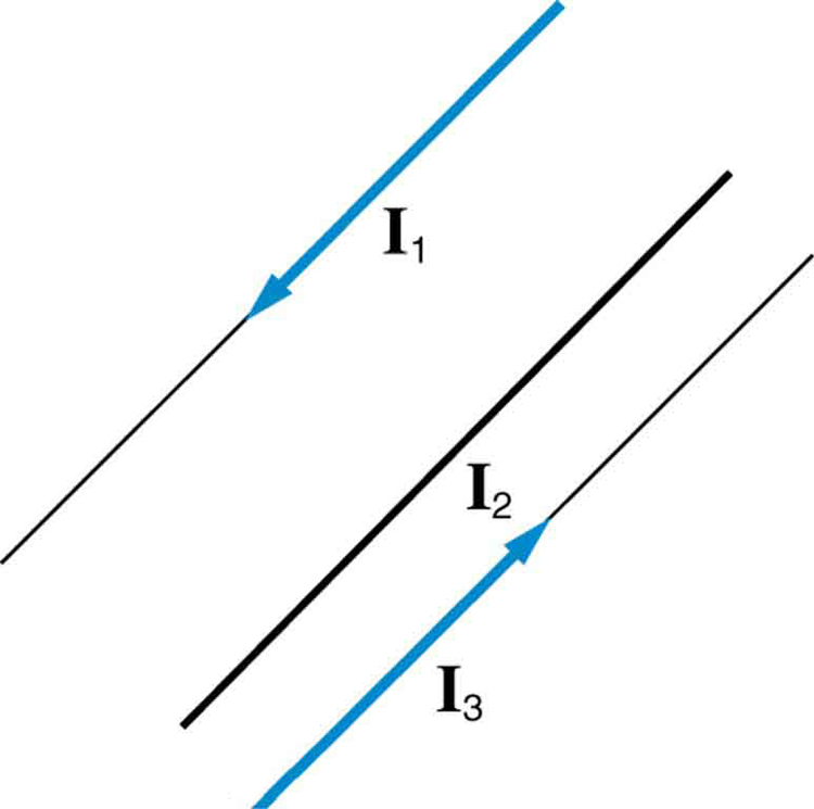
2. If you have three parallel wires in the same plane, as in Figure 2, with currents in the outer two running in opposite directions, is it possible for the middle wire to be repelled by both? Attracted by both? Explain.
3. Suppose two long straight wires run perpendicular to one another without touching. Does one exert a net force on the other? If so, what is its direction? Does one exert a net torque on the other? If so, what is its direction? Justify your responses by using the right hand rules.
4. Use the right hand rules to show that the force between the two loops in Figure 3 is attractive if the currents are in the same direction and repulsive if they are in opposite directions. Is this consistent with like poles of the loops repelling and unlike poles of the loops attracting? Draw sketches to justify your answers.
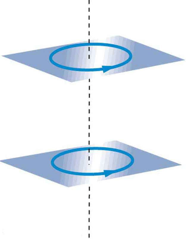
5. If one of the loops in Figure 3 is tilted slightly relative to the other and their currents are in the same direction, what are the directions of the torques they exert on each other? Does this imply that the poles of the bar magnet-like fields they create will line up with each other if the loops are allowed to rotate?
6. Electric field lines can be shielded by the Faraday cage effect. Can we have magnetic shielding? Can we have gravitational shielding?
Exercises
1. (a) The hot and neutral wires supplying DC power to a light-rail commuter train carry 800 A and are separated by 75.0 cm. What is the magnitude and direction of the force between 50.0 m of these wires? (b) Discuss the practical consequences of this force, if any.
2. The force per meter between the two wires of a jumper cable being used to start a stalled car is 0.225 N/m. (a) What is the current in the wires, given they are separated by 2.00 cm? (b) Is the force attractive or repulsive?
3. A 2.50-m segment of wire supplying current to the motor of a submerged submarine carries 1000 A and feels a 4.00-N repulsive force from a parallel wire 5.00 cm away. What is the direction and magnitude of the current in the other wire?
4. The wire carrying 400 A to the motor of a commuter train feels an attractive force of 4.00 × 10⁻³ N/m due to a parallel wire carrying 5.00 A to a headlight. (a) How far apart are the wires? (b) Are the currents in the same direction?
5. An AC appliance cord has its hot and neutral wires separated by 3.00 mm and carries a 5.00-A current. (a) What is the average force per meter between the wires in the cord? (b) What is the maximum force per meter between the wires? (c) Are the forces attractive or repulsive? (d) Do appliance cords need any special design features to compensate for these forces?
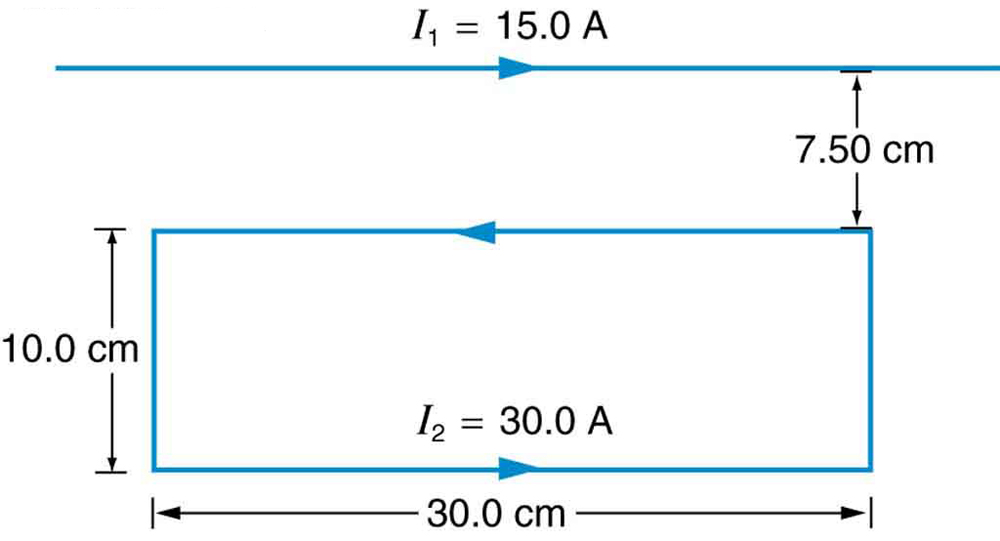
6. Figure 4 shows a long straight wire near a rectangular current loop. What is the direction and magnitude of the total force on the loop?
7. Find the direction and magnitude of the force that each wire experiences in Figure 5(a) by, using vector addition.

8. Find the direction and magnitude of the force that each wire experiences in Figure 5(b), using vector addition.
Selected Solutions to Problems & Exercises
1. (a) 8.53 N, repulsive (b) This force is repulsive and therefore there is never a risk that the two wires will touch and short circuit.
3. 400 A in the opposite direction
5. (a) 1.67 × 10⁻³ N/m (b) 3.33 × 10⁻³ N/m (c) Repulsive (d) No, these are very small forces
7. (a) Top wire: 2.65 × 10⁻⁴ N/m s, 10.9º to left of up (b) Lower left wire: 3.61 × 10⁻⁴ N/m, 13.9º down from right (c) Lower right wire: 3.46 × 10⁻⁴ N/m, 30.0º down from left
