
91 Limits of Resolution: The Rayleigh Criterion
Learning Objectives
By the end of this section, you will be able to:
- Discuss the Rayleigh criterion.
Light diffracts as it moves through space, bending around obstacles, interfering constructively and destructively. While this can be used as a spectroscopic tool—a diffraction grating disperses light according to wavelength, for example, and is used to produce spectra—diffraction also limits the detail we can obtain in images. Figure 1a shows the effect of passing light through a small circular aperture. Instead of a bright spot with sharp edges, a spot with a fuzzy edge surrounded by circles of light is obtained. This pattern is caused by diffraction similar to that produced by a single slit. Light from different parts of the circular aperture interferes constructively and destructively. The effect is most noticeable when the aperture is small, but the effect is there for large apertures, too.
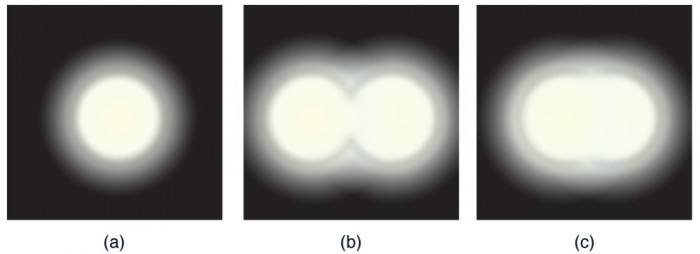
How does diffraction affect the detail that can be observed when light passes through an aperture? Figure 1b shows the diffraction pattern produced by two point light sources that are close to one another. The pattern is similar to that for a single point source, and it is just barely possible to tell that there are two light sources rather than one. If they were closer together, as in Figure 1c, we could not distinguish them, thus limiting the detail or resolution we can obtain. This limit is an inescapable consequence of the wave nature of light.
There are many situations in which diffraction limits the resolution. The acuity of our vision is limited because light passes through the pupil, the circular aperture of our eye. Be aware that the diffraction-like spreading of light is due to the limited diameter of a light beam, not the interaction with an aperture. Thus light passing through a lens with a diameter D shows this effect and spreads, blurring the image, just as light passing through an aperture of diameter D does. So diffraction limits the resolution of any system having a lens or mirror. Telescopes are also limited by diffraction, because of the finite diameter D of their primary mirror.
Take-Home Experiment: Resolution of the Eye
Draw two lines on a white sheet of paper (several mm apart). How far away can you be and still distinguish the two lines? What does this tell you about the size of the eye’s pupil? Can you be quantitative? (The size of an adult’s pupil is discussed in Physics of the Eye.)
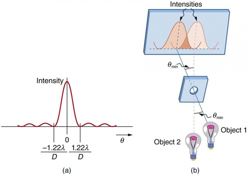
Just what is the limit? To answer that question, consider the diffraction pattern for a circular aperture, which has a central maximum that is wider and brighter than the maxima surrounding it (similar to a slit) (see Figure 2a). It can be shown that, for a circular aperture of diameter D, the first minimum in the diffraction pattern occurs at [latex]\theta=1.22\frac{\lambda}{D}\\[/latex] (providing the aperture is large compared with the wavelength of light, which is the case for most optical instruments). The accepted criterion for determining the diffraction limit to resolution based on this angle was developed by Lord Rayleigh in the 19th century. The Rayleigh criterion for the diffraction limit to resolution states that two images are just resolvable when the center of the diffraction pattern of one is directly over the first minimum of the diffraction pattern of the other. See Figure 2b. The first minimum is at an angle of [latex]\theta=1.22\frac{\lambda}{D}\\[/latex], so that two point objects are just resolvable if they are separated by the angle
[latex]\displaystyle\theta=1.22\frac{\lambda}{D}\\[/latex],
where λ is the wavelength of light (or other electromagnetic radiation) and D is the diameter of the aperture, lens, mirror, etc., with which the two objects are observed. In this expression, θ has units of radians.
Making Connections: Limits to Knowledge
All attempts to observe the size and shape of objects are limited by the wavelength of the probe. Even the small wavelength of light prohibits exact precision. When extremely small wavelength probes as with an electron microscope are used, the system is disturbed, still limiting our knowledge, much as making an electrical measurement alters a circuit. Heisenberg’s uncertainty principle asserts that this limit is fundamental and inescapable, as we shall see in quantum mechanics.
Example 1. Calculating Diffraction Limits of the Hubble Space Telescope
The primary mirror of the orbiting Hubble Space Telescope has a diameter of 2.40 m. Being in orbit, this telescope avoids the degrading effects of atmospheric distortion on its resolution.
- What is the angle between two just-resolvable point light sources (perhaps two stars)? Assume an average light wavelength of 550 nm.
- If these two stars are at the 2 million light year distance of the Andromeda galaxy, how close together can they be and still be resolved? (A light year, or ly, is the distance light travels in 1 year.)
Strategy
The Rayleigh criterion stated in the equation [latex]\theta=1.22\frac{\lambda}{D}\\[/latex] gives the smallest possible angle θ between point sources, or the best obtainable resolution. Once this angle is found, the distance between stars can be calculated, since we are given how far away they are.
Solution for Part 1
The Rayleigh criterion for the minimum resolvable angle is [latex]\theta=1.22\frac{\lambda}{D}\\[/latex].
Entering known values gives
[latex]\begin{array}{lll}\theta&=&1.22\frac{550\times10^{-9}\text{ m}}{2.40\text{ m}}\\\text{ }&=&2.80\times10^{-7}\text{ rad}\end{array}\\[/latex]
Solution for Part 2
The distance s between two objects a distance r away and separated by an angle θ is s = rθ.
Substituting known values gives
[latex]\begin{array}{lll}s&=&\left(2.0\times10^6\text{ ly}\right)\left(2.80\times10^{-7}\text{ rad}\right)\\\text{ }&=&0.56\text{ ly}\end{array}\\[/latex]
Discussion
The angle found in Part 1 is extraordinarily small (less than 1/50,000 of a degree), because the primary mirror is so large compared with the wavelength of light. As noticed, diffraction effects are most noticeable when light interacts with objects having sizes on the order of the wavelength of light. However, the effect is still there, and there is a diffraction limit to what is observable. The actual resolution of the Hubble Telescope is not quite as good as that found here. As with all instruments, there are other effects, such as non-uniformities in mirrors or aberrations in lenses that further limit resolution. However, Figure 3 gives an indication of the extent of the detail observable with the Hubble because of its size and quality and especially because it is above the Earth’s atmosphere.
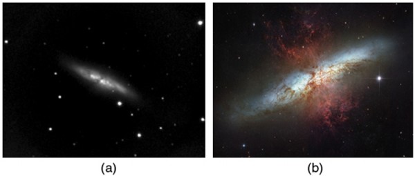
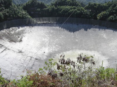
The answer in Part 2 indicates that two stars separated by about half a light year can be resolved. The average distance between stars in a galaxy is on the order of 5 light years in the outer parts and about 1 light year near the galactic center. Therefore, the Hubble can resolve most of the individual stars in Andromeda galaxy, even though it lies at such a huge distance that its light takes 2 million years for its light to reach us. Figure 4 shows another mirror used to observe radio waves from outer space.
Diffraction is not only a problem for optical instruments but also for the electromagnetic radiation itself. Any beam of light having a finite diameter D and a wavelength λ exhibits diffraction spreading. The beam spreads out with an angle θ given by the equation [latex]\theta=1.22\frac{\lambda}{D}\\[/latex]. Take, for example, a laser beam made of rays as parallel as possible (angles between rays as close to θ = 0º as possible) instead spreads out at an angle [latex]\theta=1.22\frac{\lambda}{D}\\[/latex], where D is the diameter of the beam and λ is its wavelength. This spreading is impossible to observe for a flashlight, because its beam is not very parallel to start with. However, for long-distance transmission of laser beams or microwave signals, diffraction spreading can be significant (see Figure 5). To avoid this, we can increase D. This is done for laser light sent to the Moon to measure its distance from the Earth. The laser beam is expanded through a telescope to make D much larger and θ smaller.

In Figure 5 we see that the beam produced by this microwave transmission antenna will spread out at a minimum angle [latex]\theta=1.22\frac{\lambda}{D}\\[/latex] due to diffraction. It is impossible to produce a near-parallel beam, because the beam has a limited diameter.
In most biology laboratories, resolution is presented when the use of the microscope is introduced. The ability of a lens to produce sharp images of two closely spaced point objects is called resolution. The smaller the distance x by which two objects can be separated and still be seen as distinct, the greater the resolution. The resolving power of a lens is defined as that distance x. An expression for resolving power is obtained from the Rayleigh criterion. In Figure 6a we have two point objects separated by a distance x. According to the Rayleigh criterion, resolution is possible when the minimum angular separation is
[latex]\displaystyle\theta=1.22\frac{\lambda}{D}=\frac{x}{d}\\[/latex]
where d is the distance between the specimen and the objective lens, and we have used the small angle approximation (i.e., we have assumed that x is much smaller than d), so that tan θ ≈ sin θ ≈ θ.
Therefore, the resolving power is
[latex]\displaystyle{x}=1.22\frac{\lambda{d}}{D}\\[/latex]
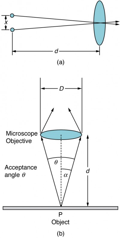
Another way to look at this is by re-examining the concept of Numerical Aperture (NA) discussed in Microscopes. There, NA is a measure of the maximum acceptance angle at which the fiber will take light and still contain it within the fiber. Figure 6b shows a lens and an object at point P. The NA here is a measure of the ability of the lens to gather light and resolve fine detail. The angle subtended by the lens at its focus is defined to be θ = 2α. From the Figure and again using the small angle approximation, we can write
[latex]\displaystyle\sin\alpha=\frac{\frac{D}{2}}{d}=\frac{D}{2d}\\[/latex]
The NA for a lens is NA = n sin α, where n is the index of refraction of the medium between the objective lens and the object at point P.
From this definition for NA, we can see that
[latex]\displaystyle{x}=1.22\frac{\lambda{d}}{D}=1.22\frac{\lambda}{2\sin\alpha}=0.61\frac{\lambda{n}}{NA}\\[/latex]
In a microscope, NA is important because it relates to the resolving power of a lens. A lens with a large NA will be able to resolve finer details. Lenses with larger NA will also be able to collect more light and so give a brighter image. Another way to describe this situation is that the larger the NA, the larger the cone of light that can be brought into the lens, and so more of the diffraction modes will be collected. Thus the microscope has more information to form a clear image, and so its resolving power will be higher.
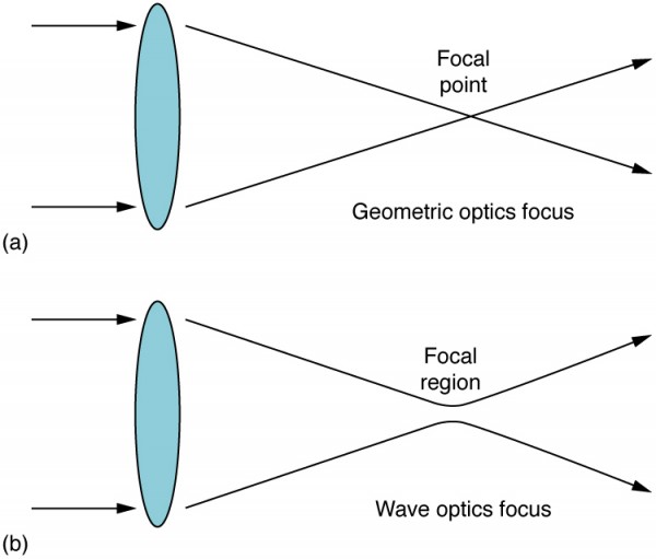
One of the consequences of diffraction is that the focal point of a beam has a finite width and intensity distribution. Consider focusing when only considering geometric optics, shown in Figure 7a. The focal point is infinitely small with a huge intensity and the capacity to incinerate most samples irrespective of the NA of the objective lens. For wave optics, due to diffraction, the focal point spreads to become a focal spot (see Figure 7b) with the size of the spot decreasing with increasing NA. Consequently, the intensity in the focal spot increases with increasing NA. The higher the NA, the greater the chances of photodegrading the specimen. However, the spot never becomes a true point.
Section Summary
- Diffraction limits resolution.
- For a circular aperture, lens, or mirror, the Rayleigh criterion states that two images are just resolvable when the center of the diffraction pattern of one is directly over the first minimum of the diffraction pattern of the other.
- This occurs for two point objects separated by the angle [latex]\theta=1.22\frac{\lambda}{D}\\[/latex], where λ is the wavelength of light (or other electromagnetic radiation) and D is the diameter of the aperture, lens, mirror, etc. This equation also gives the angular spreading of a source of light having a diameter D.
Conceptual Questions
- A beam of light always spreads out. Why can a beam not be created with parallel rays to prevent spreading? Why can lenses, mirrors, or apertures not be used to correct the spreading?
Problems & Exercises
- The 300-m-diameter Arecibo radio telescope pictured in Figure 4 detects radio waves with a 4.00 cm average wavelength. (a) What is the angle between two just-resolvable point sources for this telescope? (b) How close together could these point sources be at the 2 million light year distance of the Andromeda galaxy?
- Assuming the angular resolution found for the Hubble Telescope in Example 1, what is the smallest detail that could be observed on the Moon?
- Diffraction spreading for a flashlight is insignificant compared with other limitations in its optics, such as spherical aberrations in its mirror. To show this, calculate the minimum angular spreading of a flashlight beam that is originally 5.00 cm in diameter with an average wavelength of 600 nm.
- (a) What is the minimum angular spread of a 633-nm wavelength He-Ne laser beam that is originally 1.00 mm in diameter? (b) If this laser is aimed at a mountain cliff 15.0 km away, how big will the illuminated spot be? (c) How big a spot would be illuminated on the Moon, neglecting atmospheric effects? (This might be done to hit a corner reflector to measure the round-trip time and, hence, distance.)
- A telescope can be used to enlarge the diameter of a laser beam and limit diffraction spreading. The laser beam is sent through the telescope in opposite the normal direction and can then be projected onto a satellite or the Moon. (a) If this is done with the Mount Wilson telescope, producing a 2.54-m-diameter beam of 633-nm light, what is the minimum angular spread of the beam? (b) Neglecting atmospheric effects, what is the size of the spot this beam would make on the Moon, assuming a lunar distance of 3.84 × 10⁸ m?
- The limit to the eye’s acuity is actually related to diffraction by the pupil. (a) What is the angle between two just-resolvable points of light for a 3.00-mm-diameter pupil, assuming an average wavelength of 550 nm? (b) Take your result to be the practical limit for the eye. What is the greatest possible distance a car can be from you if you can resolve its two headlights, given they are 1.30 m apart? (c) What is the distance between two just-resolvable points held at an arm’s length (0.800 m) from your eye? (d) How does your answer to (c) compare to details you normally observe in everyday circumstances?
- What is the minimum diameter mirror on a telescope that would allow you to see details as small as 5.00 km on the Moon some 384,000 km away? Assume an average wavelength of 550 nm for the light received.
- You are told not to shoot until you see the whites of their eyes. If the eyes are separated by 6.5 cm and the diameter of your pupil is 5.0 mm, at what distance can you resolve the two eyes using light of wavelength 555 nm?
- (a) The planet Pluto and its Moon Charon are separated by 19,600 km. Neglecting atmospheric effects, should the 5.08-m-diameter Mount Palomar telescope be able to resolve these bodies when they are 4.50 × 10⁹ km from Earth? Assume an average wavelength of 550 nm. (b) In actuality, it is just barely possible to discern that Pluto and Charon are separate bodies using an Earth-based telescope. What are the reasons for this?
- The headlights of a car are 1.3 m apart. What is the maximum distance at which the eye can resolve these two headlights? Take the pupil diameter to be 0.40 cm.
- When dots are placed on a page from a laser printer, they must be close enough so that you do not see the individual dots of ink. To do this, the separation of the dots must be less than Raleigh’s criterion. Take the pupil of the eye to be 3.0 mm and the distance from the paper to the eye of 35 cm; find the minimum separation of two dots such that they cannot be resolved. How many dots per inch (dpi) does this correspond to?
- Unreasonable Results. An amateur astronomer wants to build a telescope with a diffraction limit that will allow him to see if there are people on the moons of Jupiter. (a) What diameter mirror is needed to be able to see 1.00 m detail on a Jovian Moon at a distance of 7.50 × 10⁸ km from Earth? The wavelength of light averages 600 nm. (b) What is unreasonable about this result? (c) Which assumptions are unreasonable or inconsistent?
- Construct Your Own Problem. Consider diffraction limits for an electromagnetic wave interacting with a circular object. Construct a problem in which you calculate the limit of angular resolution with a device, using this circular object (such as a lens, mirror, or antenna) to make observations. Also calculate the limit to spatial resolution (such as the size of features observable on the Moon) for observations at a specific distance from the device. Among the things to be considered are the wavelength of electromagnetic radiation used, the size of the circular object, and the distance to the system or phenomenon being observed.
Glossary
Rayleigh criterion: two images are just resolvable when the center of the diffraction pattern of one is directly over the first minimum of the diffraction pattern of the other
Selected Solutions to Problems & Exercises
1. (a) 1.63 × 10⁻⁴ rad; (b) 326 ly
3. 1.46 × 10⁻⁵ rad
5. (a) 3.04 × 10⁻⁷ rad; (b) Diameter of 235 m
7. 5.15 cm
9. (a) Yes. Should easily be able to discern; (b) The fact that it is just barely possible to discern that these are separate bodies indicates the severity of atmospheric aberrations.
