
94 *Extended Topic* Microscopy Enhanced by the Wave Characteristics of Light
Learning Objective
By the end of this section, you will be able to:
- Discuss the different types of microscopes.
Physics research underpins the advancement of developments in microscopy. As we gain knowledge of the wave nature of electromagnetic waves and methods to analyze and interpret signals, new microscopes that enable us to “see” more are being developed. It is the evolution and newer generation of microscopes that are described in this section.
The use of microscopes (microscopy) to observe small details is limited by the wave nature of light. Owing to the fact that light diffracts significantly around small objects, it becomes impossible to observe details significantly smaller than the wavelength of light. One rule of thumb has it that all details smaller than about λ are difficult to observe. Radar, for example, can detect the size of an aircraft, but not its individual rivets, since the wavelength of most radar is several centimeters or greater. Similarly, visible light cannot detect individual atoms, since atoms are about 0.1 nm in size and visible wavelengths range from 380 to 760 nm. Ironically, special techniques used to obtain the best possible resolution with microscopes take advantage of the same wave characteristics of light that ultimately limit the detail.
Making Connections: Waves
All attempts to observe the size and shape of objects are limited by the wavelength of the probe. Sonar and medical ultrasound are limited by the wavelength of sound they employ. We shall see that this is also true in electron microscopy, since electrons have a wavelength. Heisenberg’s uncertainty principle asserts that this limit is fundamental and inescapable, as we shall see in quantum mechanics.
The most obvious method of obtaining better detail is to utilize shorter wavelengths. Ultraviolet (UV) microscopes have been constructed with special lenses that transmit UV rays and utilize photographic or electronic techniques to record images. The shorter UV wavelengths allow somewhat greater detail to be observed, but drawbacks, such as the hazard of UV to living tissue and the need for special detection devices and lenses (which tend to be dispersive in the UV), severely limit the use of UV microscopes. Elsewhere, we will explore practical uses of very short wavelength EM waves, such as x rays, and other short-wavelength probes, such as electrons in electron microscopes, to detect small details.

Another difficulty in microscopy is the fact that many microscopic objects do not absorb much of the light passing through them. The lack of contrast makes image interpretation very difficult. Contrast is the difference in intensity between objects and the background on which they are observed. Stains (such as dyes, fluorophores, etc.) are commonly employed to enhance contrast, but these tend to be application specific. More general wave interference techniques can be used to produce contrast. Figure 1 shows the passage of light through a sample. Since the indices of refraction differ, the number of wavelengths in the paths differs. Light emerging from the object is thus out of phase with light from the background and will interfere differently, producing enhanced contrast, especially if the light is coherent and monochromatic—as in laser light.
Interference microscopes enhance contrast between objects and background by superimposing a reference beam of light upon the light emerging from the sample. Since light from the background and objects differ in phase, there will be different amounts of constructive and destructive interference, producing the desired contrast in final intensity. Figure 2 shows schematically how this is done. Parallel rays of light from a source are split into two beams by a half-silvered mirror. These beams are called the object and reference beams. Each beam passes through identical optical elements, except that the object beam passes through the object we wish to observe microscopically. The light beams are recombined by another half-silvered mirror and interfere. Since the light rays passing through different parts of the object have different phases, interference will be significantly different and, hence, have greater contrast between them.


Another type of microscope utilizing wave interference and differences in phases to enhance contrast is called the phase-contrast microscope. While its principle is the same as the interference microscope, the phase-contrast microscope is simpler to use and construct. Its impact (and the principle upon which it is based) was so important that its developer, the Dutch physicist Frits Zernike (1888–1966), was awarded the Nobel Prize in 1953. Figure 3 shows the basic construction of a phase-contrast microscope. Phase differences between light passing through the object and background are produced by passing the rays through different parts of a phase plate (so called because it shifts the phase of the light passing through it). These two light rays are superimposed in the image plane, producing contrast due to their interference.
A polarization microscope also enhances contrast by utilizing a wave characteristic of light. Polarization microscopes are useful for objects that are optically active or birefringent, particularly if those characteristics vary from place to place in the object. Polarized light is sent through the object and then observed through a polarizing filter that is perpendicular to the original polarization direction. Nearly transparent objects can then appear with strong color and in high contrast. Many polarization effects are wavelength dependent, producing color in the processed image. Contrast results from the action of the polarizing filter in passing only components parallel to its axis.
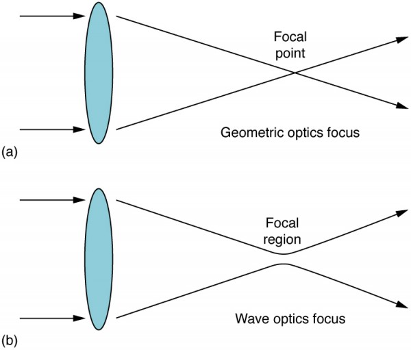
Apart from the UV microscope, the variations of microscopy discussed so far in this section are available as attachments to fairly standard microscopes or as slight variations. The next level of sophistication is provided by commercial confocal microscopes, which use the extended focal region shown in Figure 4b to obtain three-dimensional images rather than two-dimensional images.
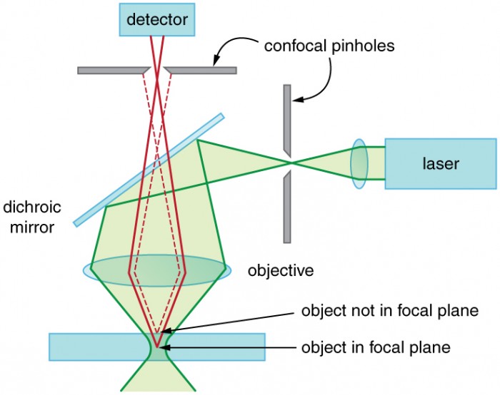
Here, only a single plane or region of focus is identified; out-of-focus regions above and below this plane are subtracted out by a computer so the image quality is much better. This type of microscope makes use of fluorescence, where a laser provides the excitation light. Laser light passing through a tiny aperture called a pinhole forms an extended focal region within the specimen. The reflected light passes through the objective lens to a second pinhole and the photomultiplier detector, see Figure 5. The second pinhole is the key here and serves to block much of the light from points that are not at the focal point of the objective lens. The pinhole is conjugate (coupled) to the focal point of the lens. The second pinhole and detector are scanned, allowing reflected light from a small region or section of the extended focal region to be imaged at any one time. The out-of-focus light is excluded. Each image is stored in a computer, and a full scanned image is generated in a short time. Live cell processes can also be imaged at adequate scanning speeds allowing the imaging of three-dimensional microscopic movement. Confocal microscopy enhances images over conventional optical microscopy, especially for thicker specimens, and so has become quite popular.
The next level of sophistication is provided by microscopes attached to instruments that isolate and detect only a small wavelength band of light—monochromators and spectral analyzers. Here, the monochromatic light from a laser is scattered from the specimen. This scattered light shifts up or down as it excites particular energy levels in the sample. The uniqueness of the observed scattered light can give detailed information about the chemical composition of a given spot on the sample with high contrast—like molecular fingerprints. Applications are in materials science, nanotechnology, and the biomedical field. Fine details in biochemical processes over time can even be detected. The ultimate in microscopy is the electron microscope—to be discussed later. Research is being conducted into the development of new prototype microscopes that can become commercially available, providing better diagnostic and research capacities.
Section Summary
- To improve microscope images, various techniques utilizing the wave characteristics of light have been developed. Many of these enhance contrast with interference effects.
Conceptual Questions
- Explain how microscopes can use wave optics to improve contrast and why this is important.
- A bright white light under water is collimated and directed upon a prism. What range of colors does one see emerging?
Glossary
confocal microscopes: microscopes that use the extended focal region to obtain three-dimensional images rather than two-dimensional images
contrast: the difference in intensity between objects and the background on which they are observed
interference microscopes: microscopes that enhance contrast between objects and background by superimposing a reference beam of light upon the light emerging from the sample
phase-contrast microscope: microscope utilizing wave interference and differences in phases to enhance contrast
polarization microscope: microscope that enhances contrast by utilizing a wave characteristic of light, useful for objects that are optically active
ultraviolet (UV) microscopes: microscopes constructed with special lenses that transmit UV rays and utilize photographic or electronic techniques to record images
